Reading an Athermalized LWIR Lens Datasheet: A 60 mm F/1.0 Case Study
Most lens selection mistakes happen before the first email.
Ask an integrator why they picked a particular LWIR lens and you usually get three answers: the focal length matched the field of view they wanted, the F-number looked fast enough, and the price was acceptable.
Then the prototype comes back with soft corners. Or the image goes out of focus at −40 °C. Or the image circle turns out to be 0.2 mm too small for the detector they actually used. Or the "athermalized" lens still needs a focus motor at temperature.
None of those failures are visible from the three numbers most people compare. They are all visible in the datasheet — if you know which lines to recompute instead of read.
This article takes a real 60 mm F/1.0 athermalized LWIR lens — the Wanbao 60A1.0LA03-N1.0 — and walks through its datasheet line by line, showing what each number actually constrains. Every step below is arithmetic you can repeat with a calculator in under a minute.
The datasheet, as published
| Property | Value |
|---|---|
| Focal length | 60 mm |
| F-number | 1.0 |
| Effective imaging surface | Φ20 mm |
| Working wavelength | 8–12 μm |
| HFOV / VFOV | 14.6° × 11.7° (with 1280 × 1024, 12 μm pitch) |
| Focusing | Fixed focal / optical athermalization |
| Lens material | Chalcogenide |
| Surface coating | HD |
| Weight | < 225 g |
| Operating temperature | −40 °C to +60 °C |
| Overall length | 75 mm |
| Front / rear diameter | Φ70 / Φ47 |
| Mount thread | M45 × 0.75 |
| Back focal length | 20 mm |
Everything below is derived from this table plus the detector format it names. No proprietary data is required.
1. The F-number is not just "how much light"
F/1.0 on a 60 mm lens means a 60 mm entrance pupil. For a thermal imager that sounds like a pure win — more flux per pixel, better NETD. It is also the point where two inconvenient things start to matter.
Diffraction. The diffraction cutoff for an incoherent system is
ν_c = 1 / (λ · F#)At λ = 10 μm and F/1.0, that is 100 lp/mm. The detector named on the datasheet has a 12 μm pitch, so its Nyquist frequency is
ν_N = 1 / (2 · 12 μm) = 41.7 lp/mmSo the optics can theoretically pass frequencies well beyond what the detector can sample — which is what you want, because it means the lens is not the limiting element. At 40 lp/mm, the diffraction-limited MTF of an F/1.0 system at 10 μm works out to about 0.50. Hold on to that number; it becomes the yardstick in section 4.
Tolerance sensitivity. A fast lens has a shallow depth of focus. Using the common wavefront criterion of ±2·λ·F#², at F/1.0 and 10 μm the budget is on the order of ±20 μm. A 20 μm defocus is irrelevant for an F/2 lens and is a real line item for an F/1.0 lens.
The practical reading: F/1.0 buys you signal and spends it on mechanical precision. If your mount has 50 μm of play, you are not getting F/1.0 performance — you are getting F/1.0 flux with F/2 sharpness. According to NIST's dimensional metrology resources, reliably measuring and holding tolerances in this ±20 μm range requires calibrated gauges and traceable measurement procedures that many integration shops do not have in place, which is why this budget is so often violated in practice rather than in principle.
2. The image circle is the most-missed line on the page
The datasheet says Φ20 mm effective imaging surface. The detector is 1280 × 1024 at 12 μm:
width    = 1280 × 12 μm = 15.360 mm
height   = 1024 × 12 μm = 12.288 mm
diagonal = √(15.360² + 12.288²) = 19.67 mm
The image circle covers the detector diagonal with 0.33 mm of total margin — 0.165 mm radially.
That is not a lot, and it has two consequences.
- Centering tolerance becomes a first-order requirement. A lateral offset of 0.1 mm consumes most of the remaining margin at the diagonal corners. When a lens measures fine on a bench and still shows soft corners in a system, this is usually why.
- Ask what "Φ20" refers to. The 100 % illumination circle, the MTF-qualified circle, and the mechanical clear aperture are three different circles. A lens can be "Φ20" in one sense and deliver degraded MTF at 19 mm in another.
If the detector were 1280 × 1024 at 17 μm pitch instead, the diagonal would be 27.9 mm and this lens would not cover it at all. The datasheet tries to prevent that mistake by naming the detector format next to the FOV — but only if you notice.
3. Recompute the FOV: it tells you whether to trust the rest of the sheet
Before believing anything else, derive the field of view from focal length and detector size.
HFOV = 2 · arctan(15.360 / 2 / 60) = 14.59°
VFOV = 2 · arctan(12.288 / 2 / 60) = 11.70°
The datasheet states 14.6° × 11.7°. It matches to the first decimal.
Do this on every datasheet you receive, because one minute of arithmetic catches three classes of problem:
- a focal length that was rounded for marketing (a "60 mm" that is really 57 mm shows up immediately)
- an FOV quoted for a different detector format than the one in the fine print
- a lens whose focal length shifts with temperature, when only the room-temperature FOV is quoted
A sheet that passes this check has earned a little credibility. One that fails it usually has other problems.
4. MTF near Nyquist — and why lens MTF is not system MTF
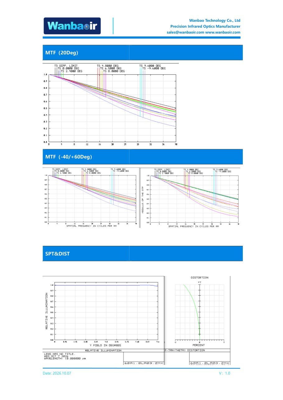
Source: Wanbao 60A1.0LA03-N1.0 datasheet, V1.0 (2026-10-07). Curves as published; measurement or simulation conditions are not stated in the document.
The datasheet shows MTF curves at three temperatures (20 °C, −40 °C, +60 °C) and states that they stay close to each other. Read at face value, the curves sit around 0.55–0.65 at 30 lp/mm and 0.45–0.55 at 40 lp/mm.
Two things must be said about those numbers. They are the difference between an engineer's reading and a brochure's reading.
First: 40 lp/mm is near Nyquist, not at Nyquist. Nyquist for a 12 μm pitch is 41.7 lp/mm. Quoting "MTF at Nyquist" from a curve that stops at 40 lp/mm is a 4 % extrapolation — small, but if you are writing a requirement document, compare at the same frequency.
Second, and more important: the lens is only one factor in the chain. In a well-designed system, modulation at the focal plane is approximately the product of three contributions:
| Contributor | At 40 lp/mm | Basis |
|---|---|---|
| Diffraction (F/1.0, λ = 10 μm) | ≈ 0.50 | ν_c = 100 lp/mm, evaluated at 0.4·ν_c |
| Detector aperture (12 μm, filled pixel) | ≈ 0.66 | ` |
| Lens (datasheet, near 40 lp/mm) | ≈ 0.45–0.55 | published curve |
Multiply the first two and you get about 0.33 before the lens even enters the picture. In other words: a perfect lens at F/1.0 on a 12 μm detector cannot deliver 0.5 system MTF at 40 lp/mm — the detector alone removes a third of the contrast.
That reframes the datasheet number usefully. A lens measuring 0.45–0.55 at 40 lp/mm is essentially at the diffraction limit of 0.50. That is a genuinely good optical design. But it also means there is no headroom left in the optics to compensate for anything else — every remaining loss comes from the detector, the window, the electronics, and the alignment.
This is where most "our lens supports high-resolution detectors" claims fall apart. Supporting a 1280 × 1024 detector is not a property of the lens. It is a property of the *chain*, and the lens is the element with the least remaining margin.
5. Relative illumination 0.98–1.00: read the definition, not the adjective
A relative illumination of 0.98–1.00 across the field is a strong result for an F/1.0 lens — wide apertures normally vignette at the corners. But the number answers a narrower question than most people assume.
Relative illumination describes the illuminance at the image plane relative to the on-axis value, from the optics alone. It does not mean:
- 98 % absolute transmission (that is a coating and material question, and would be extraordinary across 8–12 μm)
- uniform detector response (that is pixel-to-pixel responsivity, corrected by NUC)
- equal NETD at the corners (that depends on flux, F-number, and the detector)
- that you can skip non-uniformity correction
The right way to use it: it tells you the optical contribution to corner falloff is essentially zero, so any corner degradation you measure in the system is not coming from vignetting. That is a useful elimination — but it is not the same as "uniform image."
When you receive a datasheet, ask: is 0.98–1.00 simulated or measured, and normalized to what? Normalized to the field center versus normalized to the peak are different claims.
6. Operating temperature is not a performance guarantee
"−40 °C to +60 °C" is one of the most over-read lines on any thermal lens datasheet. It usually means *the lens is specified to operate* in that range. It does not automatically mean:
- MTF is maintained at every temperature in between (three points are not a continuous sweep)
- performance holds during fast thermal transients, when the barrel and the elements are at different temperatures
- performance holds after repeated thermal cycling
- the *system* stays in focus — the detector package, the mount, and the housing all move too
An optically athermalized design compensates for the temperature-induced change of focus by balancing how each element's refractive index and shape change with temperature against how the mechanical structure expands. For example, germanium — one of the most widely used materials in LWIR optics, even though this particular lens uses chalcogenide elements — has a refractive index that shifts noticeably with temperature; according to the Pihlajoki refractive-index data for germanium, this dn/dT behavior is exactly the kind of material property an athermalization budget has to account for across a −40 °C to +60 °C range. It is a system-level balance, not a property of a material. "Chalcogenide glass" alone does not make a lens athermal; the compensation comes from how optical power is distributed across the elements and how the housing is designed.
So the correct questions for a supplier are specific:
- Were the three MTF curves taken at a fixed image plane, or was focus re-optimized at each temperature?
- If focus was re-optimized per temperature, the data proves the lens *can be focused* at those temperatures — which is what a motorized focus mechanism does, and is not evidence of passive athermalization.
- Was a thermal soak applied before measurement, and for how long?
- Is the operating range a storage spec, an operating spec, or a proven performance range?
A supplier who cannot answer the first question is not necessarily hiding anything — many published curves are design outputs rather than chamber measurements. But the answer determines what the curve is evidence *for*.
7. The mechanical lines: where integration actually fails
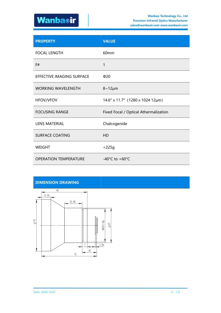
Source: Wanbao 60A1.0LA03-N1.0 datasheet, V1.0 (2026-10-07).
Three lines on the sheet are pure integration constraints, and they generate most support tickets.
Back focal length 20 mm. Ask what it is measured from — the last optical surface, or a mechanical datum? And does it account for the detector window? A 1 mm window in the optical path shifts the effective focus; if the BFL was defined without it, the first prototype will not focus.
M45 × 0.75 thread. A fine-pitch thread gives good centering repeatability but less resistance to vibration loosening, and is easy to cross-thread during assembly. If the lens will be re-focused in the field, thread wear becomes a service-life item.
Under 225 g, 75 mm long, Φ70 front. For a gimbal or a drone payload, the front element diameter usually drives moment of inertia more than mass does. Φ70 at F/1.0 also means a large exposed front surface, so coating durability and window protection matter more than the weight figure suggests.
8. Eight questions to ask before accepting any LWIR lens datasheet
This list works on any vendor, including us.
- Is the MTF curve simulated or measured? If measured: how many samples, what chamber, what soak time?
- Were the temperature curves taken at a fixed image plane, or was focus re-optimized per temperature?
- What is the image circle defined as — 100 % illumination, MTF-qualified, or clear aperture?
- Is the quoted FOV computed for the detector I am actually using? Recompute it; it takes 30 seconds.
- Is MTF specified at Nyquist, or at some frequency below it? 40 lp/mm is not 41.7 lp/mm.
- What does the back focal length reference, and does it include the detector window?
- Is the operating temperature a storage spec, an operating spec, or a proven performance range?
- What is the coating, specifically — and what is the average transmission across 8–12 μm, measured?
A vendor who answers all eight in writing is worth a prototype order. A vendor who answers three and deflects the rest is telling you something too.
What this datasheet actually says
Stripped of adjectives, the 60A1.0LA03-N1.0 sheet describes a 60 mm, F/1.0, 8–12 μm lens covering a Φ20 mm image circle, sized for 1280 × 1024 at 12 μm, with a fixed-focus optical athermalization design specified from −40 °C to +60 °C, 75 mm long, under 225 g, M45 × 0.75 mount, 20 mm back focal length.
The parts that check out arithmetically: the FOV is self-consistent with the focal length and detector format (14.59° / 11.70° against a stated 14.6° / 11.7°), and the image circle covers the detector diagonal with 0.33 mm of total margin.
The parts that cannot be verified from the document alone: whether the MTF curves are measured or simulated, whether they were taken at a fixed image plane, and what the spectral weighting was. Those are the questions in section 8 — and they are the ones that decide whether the lens suits your system.
Method note
Specifications in this article are quoted from the Wanbao 60A1.0LA03-N1.0 datasheet, revision V1.0 (2026-10-07). All calculations — image circle coverage, FOV derivation, Nyquist frequency, diffraction limit, detector aperture MTF, depth of focus — are geometric and physical derivations that any reader can reproduce; they are not internal test data. MTF values quoted are read from the published curves and are approximate. The datasheet does not state whether those curves are measured or simulated, which is precisely the point of section 8.
Related reading
- MWIR Lens for Gas Leak Detection: A Complete Guide for OGI S
- Germanium Window Engineering Guide: LWIR 8-14μm Optical Mate
- MWIR Cooled Detector Optics Engineering Guide: Lens Selectio
Have a technical inquiry?
Our sales team responds within 24 hours with specifications, pricing, and technical consultation.
CONTACT US →